
How Manufacturers Can Get a Competitive Edge Using SDKs
We spend a lot of time talking about creating applications with our technology, and we wanted to showcase an example of how this can work for developers in practice.
Here, we show how our team member Beau Trifiro used Tech Soft 3D and MachineWorks software development toolkits (SDKs) to create a manufacturing review application. This demo app is intended to:
Upload native CAD parts
Extract basic physical properties from the part
View a semi-realistic rendering of the part
Perform some basic design for manufacturability analyses
The client-side source code for this demo is available on GitHub.
What is a Software Development Toolkit (SDK)?
Before jumping in, let’s define an SDK in simple terms – an SDK is simply a pre-made code library that provides advanced capabilities through simple functions, as well as some tools and assets to help you use and implement those functions. The collection of these functions is called an application programming interface, or API.
For those who like a physical comparison, SDKs are like off-the-shelf components. if you were making an engine for a car, you're unlikely to make the motor from scratch. You’ll get one from a vendor that has the specs you need for your application. SDKs can also be referred to as "component technology", a term that gets the idea across well. As a developer, instead of hooking up a toolkit to your system with wires and bolts, you hook it up with an API.
The demo here uses three SDKs provided by Tech Soft – HOOPS Exchange, HOOPS Communicator, and MachineWorks Polygonica.
Demo Architecture
What you see when you navigate to the demo URL is a custom web page made using just vanilla JavaScript, HTML, and CSS (plus some additional assets like images). We could have used a framework like Next.js or Vue or Blazor, but chose to keep the architecture simple for the client. (In simple terms, the “client” refers to what you see when you visit a web page.) Also included in these files is the HOOPS Communicator JavaScript file for the web viewer API.
What you don’t see is the application server that’s running and uses Exchange, Polygonica, and a component of the Communicator SDK called libconverter. (The “server” is a remote computer you don’t see that performs computations behind the scenes.) These SDKs have C and C++ APIs, so we are using libmicrohttpd, a C library that provides HTTP server functionality (so the client can communicate with the server).
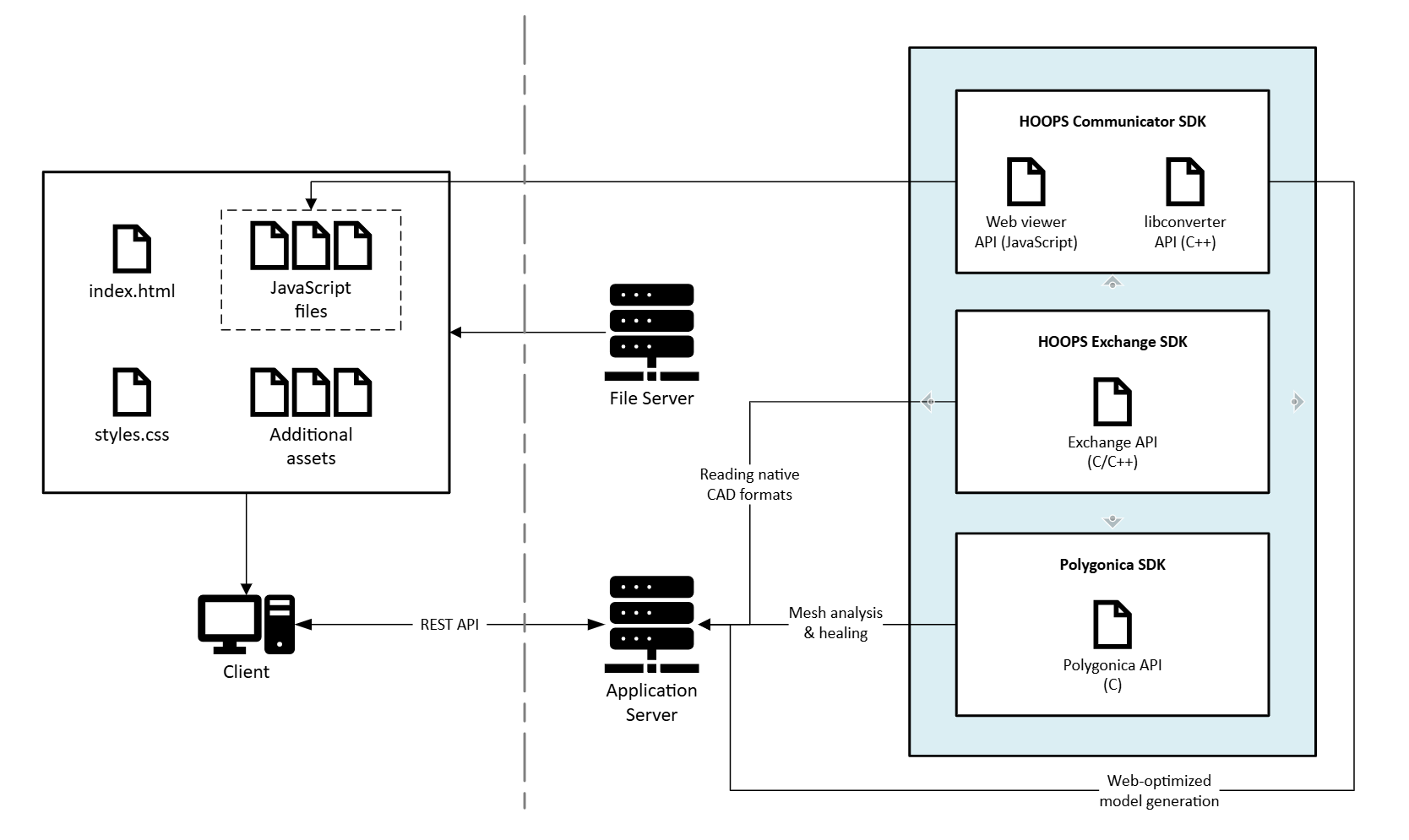
This isn’t the only way this could be done; for example, if we wanted to write the server application using Node.js, we could have used Node C++ addons to directly call the C/C++ functions or built executable processes and used Node’s child process API to call them.
This highlights two key points about working with our tookits:
Tech Soft 3D SDKs are highly flexible : you are not locked into any framework, GUI, etc. You can totally customize the look and feel.
You keep control over your application: we are not a service provided and do not access your data.
How The Application Works, Step by Step
1: Upload
On upload, the client sends the CAD model to the server. On the server, this part is read into memory with the HOOPS Exchange API (you can see a list of HOOPS Exchange’s supported file formats here). A Polygonica entity is created from this data, as well as an SCS buffer that is sent back to the client.
We generated a UUID on the server to link the client session with the Polygonica entity, and this is sent to the client, too. SCS format is one of Tech Soft 3D’s web-optimized formats for rendering CAD models in browsers. Using the HOOPS Communicator JavaScript API on the client, we can render that SCS data into a “web viewer” (a 3D scene). The standard mouse interactions like zoom, orbit, and pan are automatically provided by the HOOPS Communicator web viewer.
2: Properties
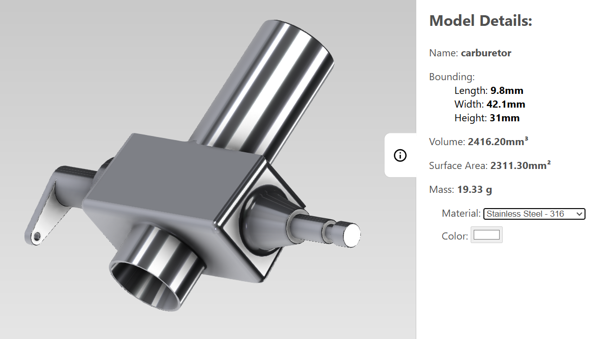
The properties panel on the right shows some of the data we can read from the CAD file using the Communicator API. This includes the model’s name, its bounding box, volume, and surface area. We’ve chosen not to display any other metadata that may be in the file. Since CAD systems and engineers don’t always have a consistent way of storing material information for a part, we allow the user to specify it in our app. We use some hardcoded values for densities of each material option, and based on the user selection, calculate the mass.
3: Physically based rendering
In order to give users a more realistic view of their part, we can easily apply realistic material propertiesto the part using the HOOPS Communicator API. For our application, we also allow users to select a custom color if they choose a plastic. Check out this demo to see more PBR capabilities.
4: Measurements
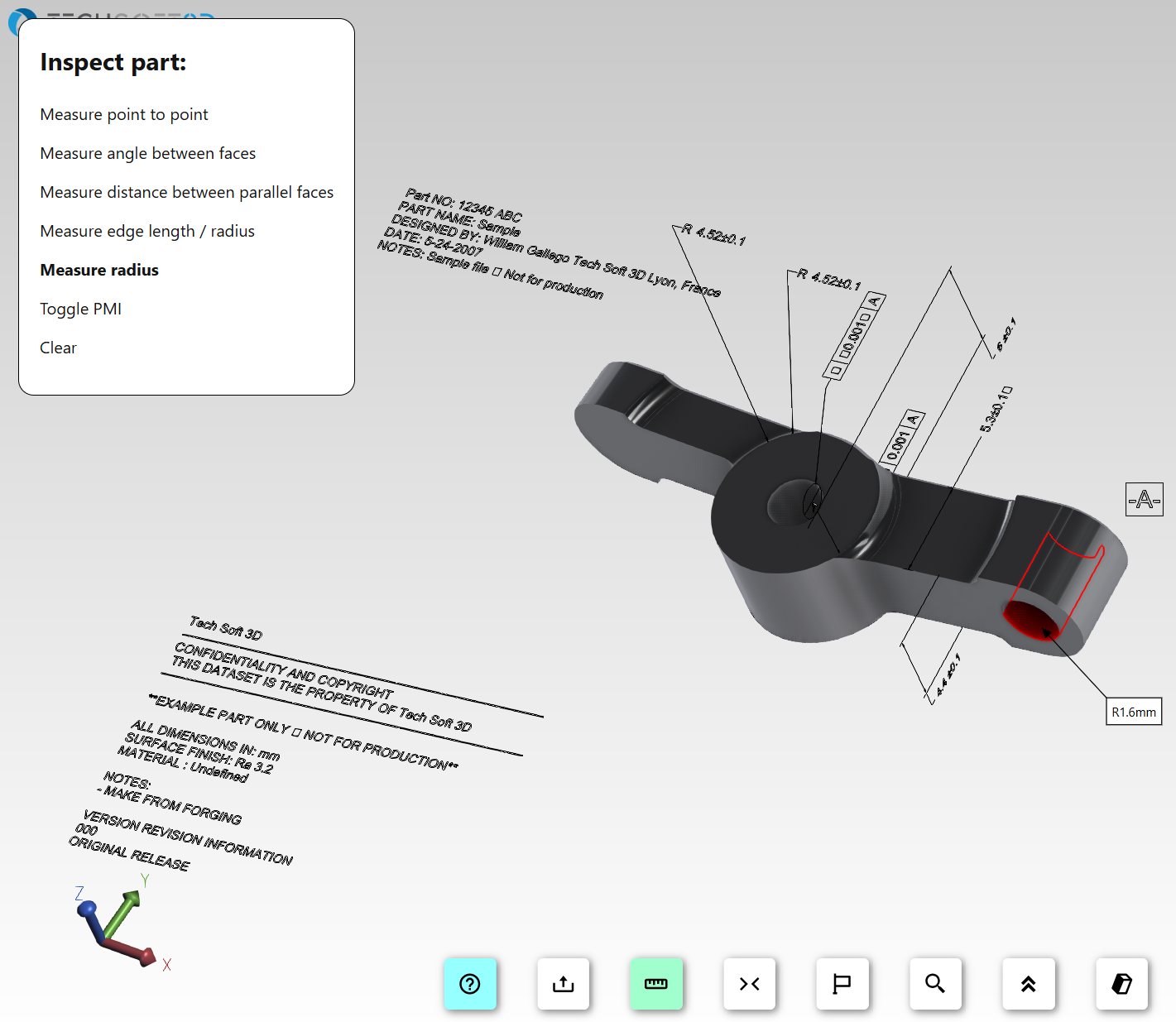
HOOPS Communicator provides measurement operators you can easily set up in your web viewer, such as point-to-point, edge length, face-to-face, and more. You can customize the behavior or create your measurement operators using the API, as we’ve done with the “measure radius” operator.
5: Product Manufacturing Info (PMI)
PMI (or GD&T) embedded within the CAD model is also readable with Tech Soft’s SDKs. We have just implemented a simple button to toggle PMI visibility, but you could greatly expand upon this functionality based on your application's needs, especially when working with formats where semantic PMI is supported.
6: Ground plane
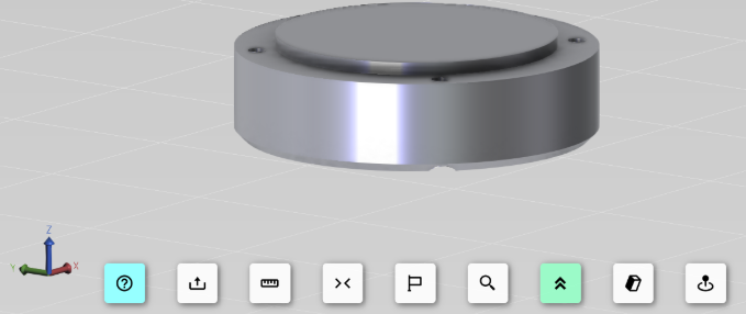
The HOOPS Communicator API allows you to generate and insert custom geometry into the 3D scene, which is how this demo’s ground plane was created. Each entity’s visibility in the scene can be easily altered.
7: Transformations
The HOOPS Communicator API allows you to apply transformation matrices to nodes so you can build custom interactivity like the orientation button does, which adjusts how the model sits on the ground plane.
8: Overhang detection
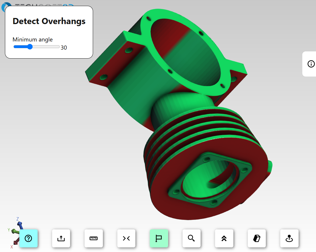
In this demo, we provided a function to detect overhangs by using the Communicator API to extract the positions and normal vectors for each vertex in the 3D model mesh, then apply a vertex color based on those values (if the vertex is not on the ground plane and has an angle less than a user-defined size, make it red). We hide the original model in the scene and display a new, colored mesh.
Each time the angle is changed, the previous colored mesh is deleted and a new one is inserted. We can click this button to toggle between the analysis display and the original display. In a 3D printing application, this could show us if a part will need supports. If you were building a DFM tool for another manufacturing process, you might implement other logic based on vertex data.
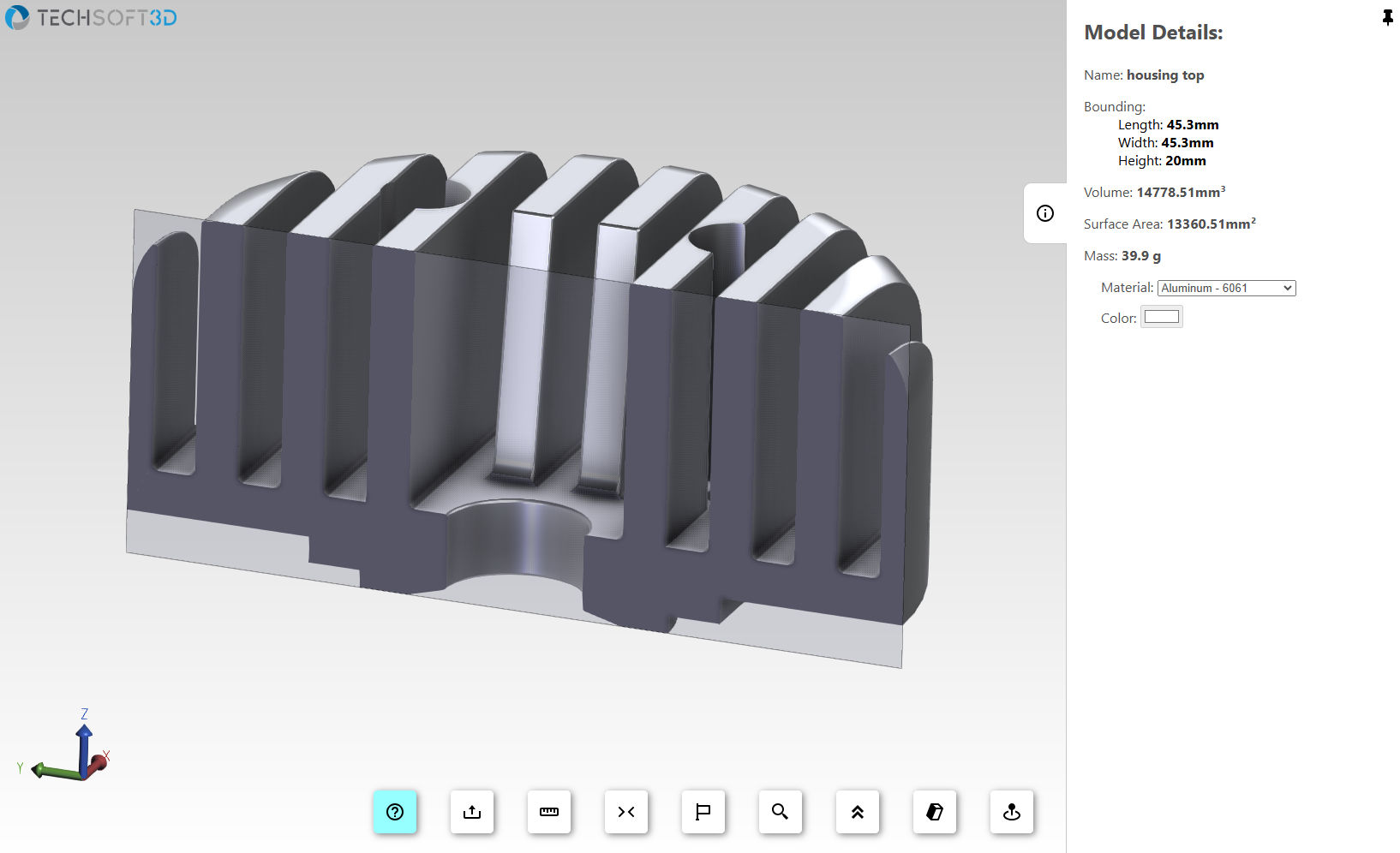
9: Cutting sections
Included in the Communicator API is a cutting operator that allows you to easily add support for section views in your 3D viewer.
10: Wall thickness:
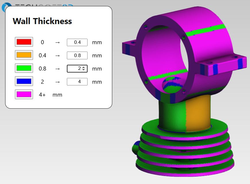
The Polygonica API provides a wall thickness analysis function that allows you to get thickness values for every vertex in the mesh representation of the CAD model.
When we click this button, we send the UUID of the model we are viewing to the server to perform the analysis on the Polygonica entity associated with that UUID. We get back mesh data that includes a thickness value for each vertex; like the overhang detection, we insert a mesh into the scene and apply vertex colors based on the thickness value.
11: Feature detection
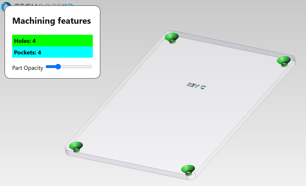
The Polygonica API provides basic feature detection capabilities. When we click this button, we send the UUID of the model we are viewing to the server to perform the feature analysis on the associated Polygonica entity. The server responds with the mesh data and an associated feature types for the features it detected, which we can use to apply a color based on the type of feature. To easily see where these features are on the part, an HTML slider is implemented that adjusts the opacity of the original part.
Next Steps and More Resources
If you have questions about this demo or would like to chat with us about licensing any of our SDKs, please contact us
The source of the SDK can make significant difference in your development experience. Learn more about the Strategic Technology Partnerships Tech Soft 3D creates and why you might want to use component technology below.
Disclaimer: This project was created for demonstration purposes, only. It is provided as-is and may contain bugs.


 Beau Trifiro •